The Case-When statement will cause the program to take one out of multiple different paths, depending on the value of a signal, variable, or expression. It’s a more elegant alternative to an If-Then-Elsif-Else statement with multiple Elsif’s.
Other programming languages have similar constructs, using keywords such as a switch, case, or select. Among other things, Case-When statements are commonly used for implementing multiplexers in VHDL. Continue reading, or watch the video to find out how!
This blog post is part of the Basic VHDL Tutorials series.
The basic syntax for the Case-When statement is:
case is when => code for this branch when => code for this branch . end case;
The is usually a variable or a signal. The Case statement may contain multiple when choices, but only one choice will be selected.
The may be a unique value like "11" :
when "11" =>Or it can be a range like 5 to 10 :
when 5 to 10 =>It can contain several values like 1|3|5 :
when 1|3|5 =>And most importantly, the others choice. It is selected whenever no other choice was matched:
when others =>The others choice is equivalent to the Else branch in the If-Then-Elsif-Else statement.
In this video tutorial, we will learn how to create a multiplexer using the Case-When statement in VHDL:
The final code we created in this tutorial:
library ieee; use ieee.std_logic_1164.all; use ieee.numeric_std.all; entity T14_CaseWhenTb is end entity; architecture sim of T14_CaseWhenTb is signal Sig1 : unsigned(7 downto 0) := x"AA"; signal Sig2 : unsigned(7 downto 0) := x"BB"; signal Sig3 : unsigned(7 downto 0) := x"CC"; signal Sig4 : unsigned(7 downto 0) := x"DD"; signal Sel : unsigned(1 downto 0) := (others => '0'); signal Output1 : unsigned(7 downto 0); signal Output2 : unsigned(7 downto 0); begin -- Stimuli for the selector signal process is begin wait for 10 ns; Sel 'X'); end if; end process; -- Equivalent MUX using a case statement process(Sel, Sig1, Sig2, Sig3, Sig4) is begin case Sel is when "00" => Output2 Output2 Output2 Output2 -- 'U', 'X', '-', etc. Output2 'X'); end case; end process; end architecture;
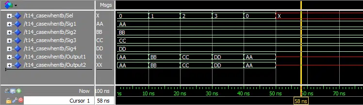
The waveform window in ModelSim after we pressed run and zoomed in on the timeline:
The output to the simulator console when we pressed the run button in ModelSim:
VSIM 2> run # ** Warning: NUMERIC_STD."=": metavalue detected, returning FALSE # Time: 50 ns Iteration: 1 Instance: /t14_casewhentb # ** Warning: NUMERIC_STD."=": metavalue detected, returning FALSE # Time: 50 ns Iteration: 1 Instance: /t14_casewhentb # ** Warning: NUMERIC_STD."=": metavalue detected, returning FALSE # Time: 50 ns Iteration: 1 Instance: /t14_casewhentb # ** Warning: NUMERIC_STD." jonas-freebie-download-widget" >
Need the Questa/ModelSim project files?
Let me send you a Zip with everything you need to get started in 30 seconds
Tested on Windows and Linux Loading Gif..
By submitting, you consent to receive marketing emails from VHDLwhiz (unsubscribe anytime).
First, we created a process using If-Then-Elsif-Else that would forward one of the signals Sig1 , Sig2 , Sig3 , or Sig4 , based on the value of the selector signal Sel .
Then we created a process that did exactly the same, using the Case-When statement. We can see from the waveform that the output signals from the two processes, Output1 and Output2 , behave exactly the same.
In our example, the Sel signal has only four legal values. But if there had been a higher number of possibilities, we can easily see that the Case-When statement can help making code more readable. This is the preferred way of creating such a component by most VHDL designers.
Understanding of the multiplexer was the bonus point of this exercise. Multiplexers, or MUX’s for short, are central components in digital design. It is simply a switch that selects one of several inputs, and forwards it to the output.
This is an illustration of how our MUX forwards the selected input signal:
We used the others clause to catch all values of Sel which were not ones or zeros. As we learned in the std_logic tutorial, these signals can have a number of values which are not '0' or '1' . It’s good design practice to deal with these values by outputting 'X' . This indicates an unknown value on this signal, and it will be visible in downstream logic as well.
We can see from the waveform that when the Sel signal turned red, Output1 and Output2 also changed to "XX" . This is when others => in action.
Additionally, the console output in ModelSim shows a warning because of the Sel signal being set to "UU" . The “ ** Warning: NUMERIC_STD.”=”: metavalue detected, returning FALSE ” messages appear at 50 ns simulation time, which is exactly when the signals turn red.
Get free access to the Basic VHDL Course
Download the course material and get started.
You will receive a Zip with exercises for the 23 video lessons as VHDL files where you fill in the blanks, code answers, and a link to the course.
By submitting, you consent to receive marketing emails from VHDLwhiz (unsubscribe anytime).
I’m from Norway, but I live in Bangkok, Thailand. Before I started VHDLwhiz, I worked as an FPGA engineer in the defense industry. I earned my master’s degree in informatics at the University of Oslo.
 Should I learn VHDL if Verilog is becoming more popular?" width="748" height="421" />
Which HDL is the most popular, and should I learn VHDL or Verilog? That’s a question I often get asked, and it’s understandable. People want to future-proof their learning by betting on the winning horse. But which one is it, and does it matter?
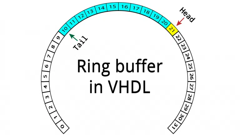
Circular buffers are popular constructs for creating queues in sequential programming languages, but they can also be implemented in hardware. In this article, we will create a ring buffer in VHDL to implement a FIFO in block RAM. There are many design decisions you will have to make when implementing a FIFO. What kind of…
Functions are subprograms in VHDL which can be used for implementing frequently used algorithms. A function takes zero or more input values, and it always returns a value. In addition to the return value, what sets a function apart from a procedure, is that it cannot contain Wait-statements. This means that functions always consume zero…
A concurrent statement in VHDL is a signal assignment within the architecture, but outside of a normal process construct. The concurrent statement is also referred to as a concurrent assignment or concurrent process. When you create a concurrent statement, you are actually creating a process with certain, clearly defined characteristics. Concurrent statements are always equivalent…
I was a little annoyed by the peculiarities of the AXI interface the first time I had to create logic to interface an AXI module. Instead of the regular busy/valid, full/valid, or empty/valid control signals, the AXI interface uses two control signals named “ready” and “valid”. My frustration soon changed to awe. The AXI interface…

When designing VHDL for safety-critical FPGA applications, it’s not enough to write testbenches at best-effort. You have to present proof that the module works as intended and without undesirable side-effects. Formal verification techniques can help you map a requirement to a test, proving that your VHDL module conforms to the specification. It’s an instrumental tool…
Thanks for your tutorials. Quick question: When a ‘when xxx =>’ block is evaluated, can one and only one choice be evaluated for each scheduled event? In other words, if something changes in the first ‘when xxx =>’ block that could cause the condition in the second ‘when xxx =>’ block immediately below to be true, does this get ignored until the next event, or will VHDL run through every ‘when xxx =>’ block (like a C switch statement with no ‘break’ between cases)? Keep up the good work.
Jonas Julian Jensen says:Hi Joel, Interesting question! The Case statement is not like a C switch, hence there is no ‘break’ keyword. Only one When-branch will be run each time the program reaches the Case statement. What happens in a situation where the condition (the ‘Sel’ signal) is changed from within a When-branch, depends on the process that the Case is inside of. If we managed to change the Sel signal inside of the ‘when “10” =>’ for example (even though that would not work because of multiple drivers). Then, the process would immediately run once more because the Sel signal which the process is sensitive to has changed. This time, another When branch would be selected. If the above algorithm results in an infinite loop, the simulator may produce a warning, or it may freeze or hang. I have seen both happen. The thousand dollar question is of course what kind of logic this would produce if used in an RTL (production) module. The results can be unpredictable. Therefore you should only use such creative code in testbenches 🙂
Joel says: Makes sense. Thanks for your time! Hus says:Hallo Jonas, if I have input of 8 bits and i want to use case statment it would be something ugly like this: CASE input IS
WHEN “000000000” => output output output output …
…
WHEN others ………….;
CASE; I should write 255 lines to cover all cases. Is there a smarter way to manage this?
Is it possible to use operation of the component inside case statement? For example i have created a component that do some specific operation for certain period of time.
and I want to use the component to get result when the switch is on case2 or case 3. Please give some idea regarding this.